So, you’ve decided to repair/upgrade your vintage audio equipment by replacing the capacitors. When you go to Mouser or Digikey, however, you are presented with tens of thousands of choices. Even after drilling down to the specified capacitance and voltage, you have dozens of candidates, differentiated by such esoteric terms as Tan Delta, Q Value, ESR, etc, etc, etc. Here’s what you need to know to pick the best capacitor for the job, without spending a fortune on Super Fancy Audio Capacitors.
First, a quick review of what capacitors are and how they work: You can think of a capacitor as a bucket o’ electrons. All capacitors have two layers of conducting material, with a layer of non-conducting material between. The non-conducting material is referred to as the dialectric. What makes a material conduct is that it has a large number of possible electron configurations, so that at any time in a metal there are a cloud of loose electrons wandering from atom to atom. When you apply a positive voltage to one side of the non-conducting plate, it pulls electrons off of that plate, much like lower air pressure in a room that you’ve just taken the air pressure out of (electrons are negatively charged, and so they are attracted to a positive voltage). The lack of electrons on the positive plate induces a greater number of electrons on the negative plate, giving it a net negative charge.
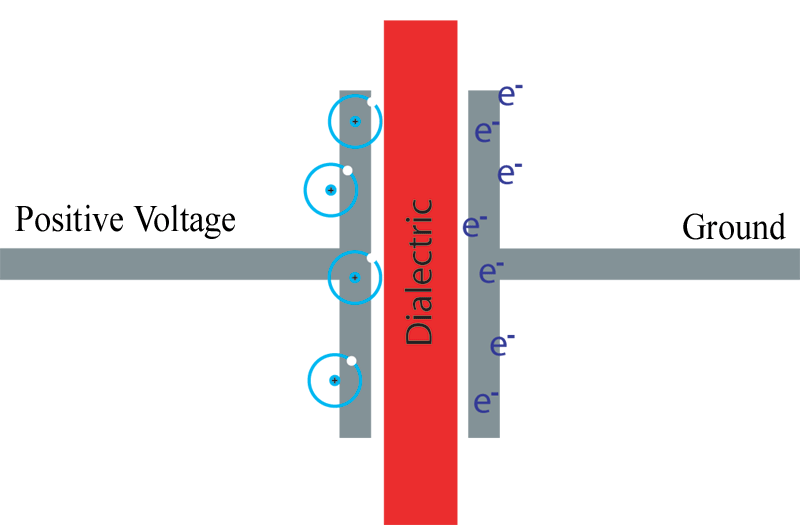
The astute reader will notice that as the electrons are actually travelling towards the positive voltage. The direction of current travel shown in most electrical schematics is actually the opposite of the direction of charge carrying particles. We have Ben Franklin to thank for this incorrect convention, and in some European schematics, particularly older ones, the current orientation is shown correctly.
This is probably the point where I should talk about electrical safety when working with large capacitors. Capacitors store electrons, and if you place yourself between those electrons and a ground, they will shock you, and it will hurt. What makes this particularly easy to do is the fact that the entire metal chassis of the amp is the ground, much the way your car is wired. So here’s what you should do after you unplug the amplifier and before you start rooting around in there:
Check the positive terminals of all your large filter capacitors with a multimeter, on DC voltage. If it reads less than 12V, it won’t shock you, but you still might fry another component by shorting it to the capacitor with your metal tools.
If you have a cap that still has some juice in it, connect a 1Kohm (1000ohm), 5W resistor across the leads and let it discharge until the voltage reads zero.
Capacitor Metrics: There are four main specifications for capacitors.
- Voltage: This is the maximum voltage that a capacitor may be subjected to without dialectric breakdown. Dialectric breakdown occurs when the electrical field between the two plates of the capacitor become strong enough for the dialectric to polarize and become a conductor. When this happens, the capacitor will become hot. Then it will smoke. Then it will catch fire or in some cases explode. So when you are ordering the capacitors, you should pick ones with an equal or higher rated voltage. There’s no advantage in going with a larger voltage, and doing so will mean a larger capacitor, which can be harder to fit in the amp.
- Capacitance: The unit of capacitance is the Farad, one Coloumb-Volt. A coloumb is a truly ridiculous number of electrons, so typically capacitors are measured in microfarads- mF or uF or (Greek letter mu)F. A microfarad is 1/1,000,000 or 1×10^-6 of a Farad. Picofarads are also used, which are 1/1,000,000 or 1×10^-6 of a microfarad (1×10^-12 of a Farad). So you can divide or multiply by a million to move between these quantities.
- Tolerance: This is the acceptable variation on the value. So a 47mf capacitor with -20%/+80% tolerance would have a capacitance of anywhere from 37.6mf to 84.6mf (although the values for new electronics are typically quite close to the specified value).
Dialectric: The fourth way that capacitors are specified is by dialectric, the type of material separating the metal plates. There are three common types of dialectric.
Ceramic: the dialectric is porcelain, giving these capacitors long life and high voltage, although with low capacitance. Often, they are a tan/brown color, and usually disk-shaped although sometimes tubular shapes are used (the tubular ceramic capacitors may be replace with ceramic disk capacitors). Generally, these capacitors do not degrade over time, although they can be checked for mechanical/heat damage, and also continuity. Because they can store charge, the continuity tester may briefly beep or light up, but should not stay on.
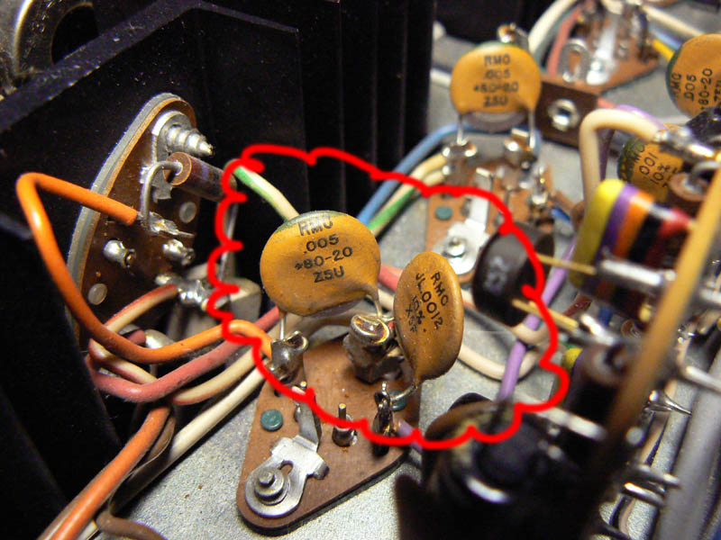
In the picture, two capacitors are shown. The one on the left reads:
RMC = manafacturer
.005 = .005mF
+80-20 = +80%, -20% tolerance
Z5U = the subtype of ceramic dialectric (you don’t have to match this if it’s a pain).
What’s missing here is the voltage rating, so you’ll have to go to your service manual for that. If you can’t find it, you’re usually safe with 250V or higher.
The one on the right reads:
RMC = manafacturer
JL.0012 = .0012mf (the JL means something but I don’t know what)
10% = +/- 10% tolerance
X5F = Dialectric subtype
There’s a good reference to ceramic capacitor markings here.
Film Dialectric: in film dialectric capacitors, the dialectric is some kind of plastic, such as mylar or polypropylene. This dialectric allows a high voltage and long life, but at a downside of being relatively large and expensive. There are a bewildering array of possible dialectrics in this catagory, but on the recommendations of people who know more about this stuff than I do, metallized polypropylene is a good and inexpensive choice for audio applications.
Film capacitors generally do not wear out, so replacing them is more in the upgrade catagory then restoration. However, because electronics in this area have improved tremendously in the past however may years since your amp was built, it can still be worth doing.
Be advised that as film capacitors are often used in the signal path, and the newer film capacitors have improved electrical characteristics, you may change the sound of your amp by replacing them. Maybe for the better, maybe for the worse. There’s a lot of art here in the intersection between the objective electrical characteristics of the capacitor and the subjective assessment of how good it sounds. The good news is that electronics parts are cheap, so if you don’t like what you get you can try something else.
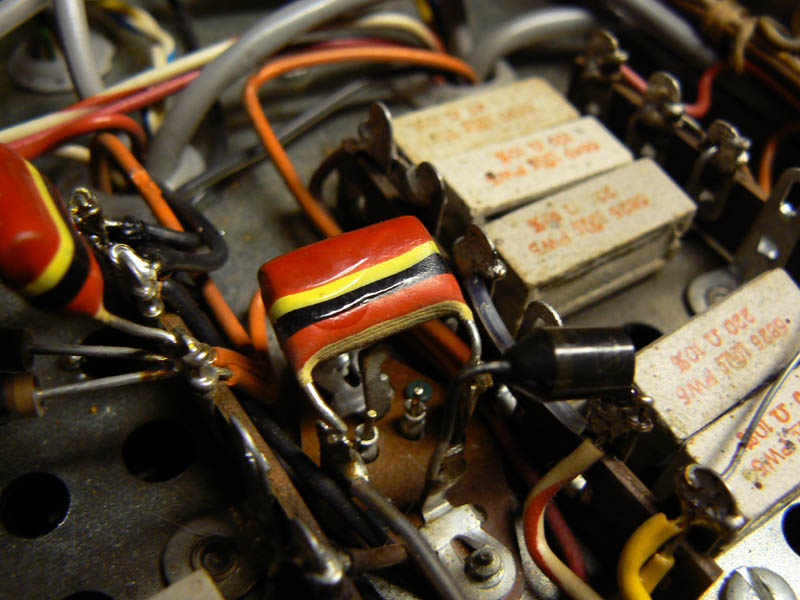
The picture above shows a film capacitor with the color band style of marking. These can be a little tricky, and the web has a number of different and sometimes contradictory answers on how to read them. But in general, they work like resistor color codes.
In the diagram, the color bands are:
Red: first digit = 2
Red: second digit = 2
(there’s no line between the two red bands, you are supposed to recognize that this is actually two bands).
Yellow: multiplier = 5, i.e. multiply by 1×10^5mF
Black: maybe tolerance?
Red: first digit = 2
Yellow: second digit = 5, so 250V?
So I get .22mF 250V.
I guess, anyway. I actually went to the schematic and read the specs off that.
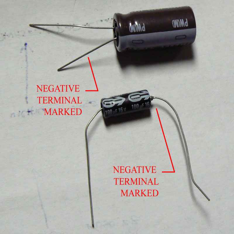
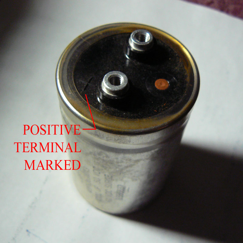
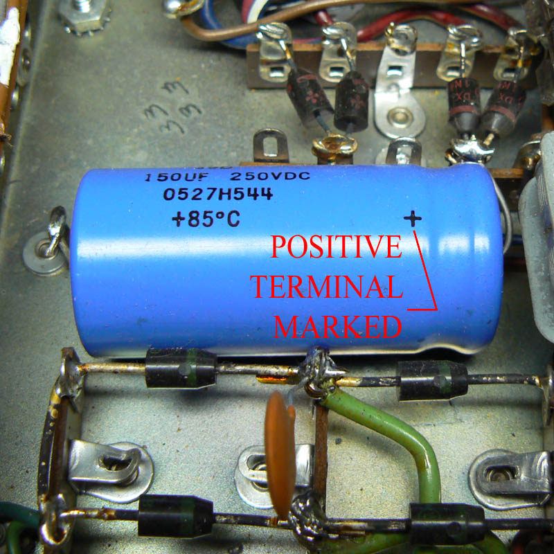
Electrolytic Dialectric: In this type of capacitor, a chemical insulator is applied to one of the foil plates. This allows for a much thinner dialectric than other types of capacitors. Capacitance, you’ll remember from E&M, is directly proportional to the area of the plates and inversely proportional to the distance between them, so this design allows extremely high capacitance in a very small volume at low cost. This makes electrolytic capacitors ideal for power filtering, as the larger the cap, the less ripple current. Electrolytic capacitors come in a variety of forms, the attached images show a few of the more common varieties.
There are a number of downsides with electrolytic caps.
- They wear out. As time works it’s ravages, the electrolytic breaks down, causing the capacitor to lose its ability to store electrons and become more of a resistor than a capacitor. If you buy an amp at a garage sale, it’s always a good idea to at least replace the filter caps before you turn it on for the first time, because otherwise you can fry your transformer. You’ll read about how you can ‘reform’ electrolytic capacitors by applying a small voltage to the capacitor for 15 minutes to rebuild the polarity of the dialectric. My take: don’t screw around with it, just replace them. Electronics parts are cheap, your amp is not.
- They are (generally) polarized. One lead of the capacitor must always be at a lower voltage than the other, otherwise the electrolytic will break down. An electrolytic capacitor connected in reverse will get hot and emit a very distinct smell, something like fish frying in a vat full of chemicals. This is the electolytic vaporizing. The polarity is marked in a variety of ways, look at the above images. The one exception to this rule is bipolar or non-polar electrolytics, which will be clearly marked with a “BP” or “NP” on the schematic. These are very much the exception; in the Mac 1700 there are only two, in the power protection circuit.
- They are leaky. Even a new electrolytic cap allows a considerable amount of current across the plates; this makes them less than ideal for audio signal path usage. You can replace the electrolytics in your amplification stages with film capacitors; as I said above, doing so might improve your sound, or not. Parts are cheap, try it and see what you get.
Other capacitor characteristics: Because of the wide number of applications of electrolytic capacitors, there are a wide variety of characteristics that you’ll have to choose between when you’re matching the parts. Here’s my take on them:
- Low Impedance: Impedance is composed of two parts, resistance and reactance. Resistance is probably familiar to most of us, it is the opposition to direct current (i.e. current that does not vary with respect to time) in a circuit, governed by the relation:
Voltage = Current * Resistance
Reactance is the analogous property for time varying currents, such as audio currents. Now, ideally capacitors do not transmit direct current at all, as there is no direct connection between the plates. So impedance as it applies to capacitors is mostly a function of reactance. I say mostly, because real-world capacitors do leak some DC, but not enough that we can’t use the ideal model. The formula for reactance in ideal capacitors is:
Reactance = 1 / (2 * pi * frequency in Hz * Capacitance)
So a capacitor will have a greater reactance to low frequencies, and the larger the capacitor the lower the reactance. What impedance really represents for an audio application is how much distortion a capacitor injects into a frequency passing through it, by pushing back against a time-varying current. This makes low impedance one of the more important characteristics of a capacitor in the signal path, less so for a filter capacitor.
- 85 C / 105 C: The maximum operating temperature of the capacitor. Now, keep in mind that 85C is 185 degrees fahrenheit, more than enough to cause burns. My take on this is, if your capacitors are running this hot, there’s something else wrong in your system, or you’ve got the capacitor in backwards. So 85C is fine for audio applications.
- Low ESR: ESR stands for Equivalent Series Resistance. This can mean different things depending on the type of component, but in a capacitor, it is the voltage loss due to resistance in the metal leads and plates. A typical ESR for a capacitor might be .1Ohm, whereas a low ESR model might be .01ohm.Low ESR seems to be a much touted feature for audio capacitors, especially Black Gates. Since resistance is not dependent on frequency, however, I don’t understand how ESR would have any effect on distortion in the audio signal, and I doubt you’re going to hear a difference between .1 and .01 ohm. If you want to make a case for it, the comments are your oyster.
- Low Leakage: An ideal capacitor doesn’t have any electrical connection between the plates, so there would be zero DC current across the capacitor. This is not an ideal world, and so real capacitors do leak DC. The formula given in the spec sheets is of the form:
Leakage current = Constant * Capacitance * Voltage,
The constant is typically on the order of .01 or less, and varies with the line of capacitor.
For audio purposes, we don’t care how much leakage occurs when the amp is turned off. It can be significant for filter capacitors, however. Leakage current is proportional to the capacitance and voltage, and filter capacitors have a lot of both. In addition, they are being charged at the relatively low frequency of 120Hz, and so how well they keep that charge between the variations in the power affects the amount of ripple current you hear on the other end of the capacitor.
- High Ripple current: this specification can be a little confusing, since I already defined ripple current as the variation in filtered DC voltage on the load side of your filter capacitors, and the lower the better.Here, however, it means that the capacitor can withstand high time varying currents without heating itself up so much that it fails (via Ohmic heating due to reactance). This is one of those specs, like rated voltage, where as long as you meet it it won’t affect you one way or the other. Thing is, you won’t find the rated ripple current for any of your original capacitors. I’m going to hazard a guess that, as electronic components have improved considerably since your amp was built, the rated ripple current of almost any new capacitor that you put in there will be higher than spec. But if it’s a tiebreaker, go with the higher ripple current.
- Long Life: There are two aspects to long life, a long shelf life or a long rated life.Long Shelf Life: As mentioned previously, the dialectric of an electrolytic capacitor will break down if the positive lead is not kept at a higher voltage than the negative lead. Capacitors aren’t generally going to sit around long enough before you put them in your amp for this spec to matter. But if your amp goes through long periods of disuse, perhaps because you can’t stop buying them at garage sales, then this is the capacitor for you.Long Rated life: This is the number of hours that a capacitor will function under load without dropping below, say, 80% of it’s rated capacitance. If you go with a long rated life, you might have to replace your electrolytics every 30 years instead of every 20.
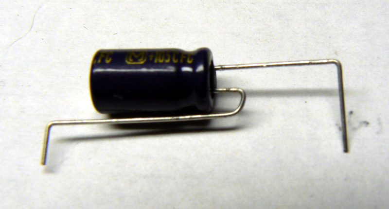
- Radial/Axial: This refers to where the leads are on the capacitor. In an axial capacitor, the positive and negative leads are at opposite ends of the cap, whereas in a radial capacitor they are on the same side. Both varieties are shown in post #19, in the first picture. There’s no difference in electrical/sonic characteristics, so it’s just a matter of how the capacitor is physically going to fit in the space provided for it.On my 1700, the original capacitors were all axial. I used all radial capacitors (I was unable to find ones with the characteristics I wanted in axial form), and it worked out fine for me. I bent the leads as shown in the picture so that I wouldn’t have capacitors sticking out all over the place, but that was a cosmetic decision, there’s plenty of room in the chassis to have them sticking up.
- Tan delta/Loss dissipation factor/Q factor: This is a number representing the total efficiency of the capacitor. You know how a capacitor gets warm when in use? That heat energy doesn’t come for free, it is the energy lost in charging and discharging the capacitor due to resistance and reactance. I’m ending with this specification because it attempts a holistic measurement of a lot of factors, such as impedance, leakage, and ESR. Tan(delta), dissipation factor, and Q factor are exactly the same thing, expressed in slightly different ways:
tan(delta) = charge lost to heat / charge returned
So a tan(delta) of .1 would mean that 1/10th of the energy is lost to heat. Lower is better.
Dissipation factor = tan(delta) * 100%
So the dissipation factor is the percent of energy dissipated. Lower is better.
Q factor (or Quality factor) = 1 / Dissipation factor
So the quality factor is the percentage returned as usable electrical energy. Higher is better.
Q factor + Dissipation factor = 100%
So if you have two capacitors with different Q factors, the one with the higher Q factor is probably your better bet. Alternatively, you could connect them to equivalent AC loads, and see which one stays cooler. But because the dissipation factor can arise from a variety of sources, different capacitors with the same Q factor could be better suited for different applications.
The Upshot: Here’s what to look for, if you were kinda skimming for the last 2,000 words or so.
Signal capacitors: low impedance, long life.
Filter capacitors: low leakage, long life.
Quick and dirty test for people who don’t want to wade through the specs: Low tan(delta), low dissipation factor, or high Q factor.
Where possible, I replaced the electrolytics in my MAC1700 with Panasonic FC or FM series and Nichicon PW or HE series. I also later replaced the film capacitors, which were crumbling into dust due to the amp being stored in a garage in Texas for many years. For those I used Xicon MPP series. My parts list for the MAC1700 may be downloaded here:
For the whole project, including shipping, my cost was about $90. If you want to be a little smarter about where you spend your money (“Computer Grade” capacitors are really fine for the power filtering sections, e.g.), you could probably cut that in half.
 From
From
on my Macintosh amp, do I really have to replace the can caps? they’re no longer available and the replacements are a bundle. I can try reforming them, but what kind of juice are you recommending to run through them for 15 mins, and for what period of time? Thanks
This was super helpful, thanks. I mostly know what I’m doing around minor electronic repair but the piles of numbers on Mouser, Digikey or whatever site was pretty daunting. My Onkyo is going to get some new caps now!
Hi Ray,
See here for how to replace multi-can style capacitors inexpensively, with a stock look: I’m pretty skeptical about the whole ‘reforming’ capacitors thing, and the new ones you can buy are much better quality than what was available when the amp was made.
Good luck!
Max
Any information on the availability of a canned capacitor about the size of a wooden safety match box with mounting feet located on the narrow side and solder connections on what would be the bottom end. Appreciate any help
That sounds like a pretty crazy capacitor, Wally! Can you post up a picture?
Can I get away with replacing a 100uf 25v cap with a 100uf 16v cap? it’s in the power supply board of an onkyo. thanks for the info.
I wouldn’t– 100uF capacitors are easy to find (like Radio Shack if you don’t want to wait for shipping), and since you’re using it in a power supply it doesn’t need to be anything fancy. Why take the risk? My $.02
I have a fisher 440-t (transistor receiver)
i want to replace the big power supply cap (2500uf) 65 volts but cant find anything comparable. can i put in a larger capacitor. I think this is what is called a filter capacitor to smooth the voltage.
any help appreciated.
Hi James,
Use the same capacitance rating (or the closest standard value), and any voltage higher than 65V. Since it’s not in the audio signal path, it’s not super critical.
Best,
Max
hello sir. i am struggling to find a high frequency capacitor for my jbl home speaker. it is a radial elecrolytic 3.9uF, 100v, np and is about 10mm in diameter. i have found larger diameters but nothing in the 10mm range. i sure would appreciate any ideas. can i use something else? thank you
Hi! The geometry of the capacitor doesn’t matter at all to the sound, so you can use any capacitor that is (1) 3.9uF (2) rated 100V or more and (3) non-polarized. If you pick one that is also “Low ESR” it would better approximate a perfect L-C circuit, and so in theory that might sound better “crisper” or “punchier” as the capacitor isn’t soaking as much of the load (emphasis on: in theory). Does that help?
Hello Max, I am looking at replacing the power supply and audio path caps on an old school PPI car amp. I understand how to select the replacement parts but I am still left with many product lines to choose from, all suitable for the application. Have you personally ever put any stock in “Audio Grade” electrolytic caps? Specifically the Nichicon KA and KZ series..
Hi Max
Belated thanks for your reply re my Fisher 440-t
Thanks for your help
Best
James
I have a Amp from the ” OLD SCHOOL ROYAL FAMILY ” and they’re known for”Bad Caps” after time. It’s an XTANT-3300c = 3channel (60×2 & 180×1 @4ohm)
[ 1000uf 50v 85c ]
[ 100uf 63v 85c ]
[ 10uf 50v 85c ]
Shoot, from my above comm about the [XTANT CAPs]
A= can I use higher volts?
B= can I use higher ufs
C= can I use higher of both?
D= I’m just going for good right crisp low , mid , highs like it use to have.
E= ANY other tips toy have that may help is be very greatful. Thanks
Scott: Nichicon KA/KZ is a great choice for capacitors in the signal path. For power supply caps, there are cheaper options that will work just as well.
Michael: The post above should answer your ABCDE questions about how to select replacement capacitors. If you’re completely confused maybe have a pro do this?
I have an Onkyo A-35 amp from the early 1980’s that seems to be working fine except that one channel seems lower in volume to the other. Should I be looking into replacing the caps if not for this, for safety reasons?
“Since resistance is not dependent on frequency, however, I don’t understand how ESR would have any effect on distortion in the audio signal, and I doubt you’re going to hear a difference between .1 and .01 ohm. If you want to make a case for it, the comments are your oyster.”
The resistance or ESR in a cap, is very much dependent on frequency. Caps aren’t ideal components, and no component is – there’s always a combination R/H/C in anything, down to PCB traces or wire gauge. For practical purposes, these effects are usually negligible, but in the case of ESR with Audio it’s important to find a curve for the component to see how it behaves in the audio band – it’s actually extremely important to know what frequency the ESR measure is taken at because an ESR measure at 100kHz (fairly typical) saying “0.1 Ohms” is going to effect your circuit very differently in the audio band, than something spec’d from a measurement 0.1 Ohms@10kHz.
From Texas Instruments : “A capacitor begins capacitive (XC) then becomes resistive (ESR) near its resonance point and finally becomes inductive (XL) at high frequencies. The impedance curve (Z) is the combination of each of these components. Capacitors are usually rated with a maximum ESR at a certain frequency.”
You’re right that it won’t cause distortion per se, but the phase shift factor can become significant with ESR – run a square wave through a set of components that don’t have frequency dependent phase shift (i.e. almost any cap), and look at what happens to the shape – you will most likely have more pronounced peaks, edges, ringing, etc… when these become great if you don’t have the headroom in a particular stage, then yes, you introduce clipping i.e. distortion.
The values you cite are for ceramics – anything tantalum for instance, typically exhibits ESR that is orders of magnitude more, unless it’s pricey. Electrolytics can be very, very bad with ESR also unless you pump out the $. What the capacitor is actually doing in the unit should also dictate what properties you are looking for, or which of the variables you discuss are more relevant. Doug Self has a great section on cap selection in his book “Small Signal Audio Design” with guidelines based on function.
I totally agree with you that there’s hype surrounding almost any high end audio equipment, but there are some details in here I think you should reconsider.
The comment waaaay up there ↑↑ about a metal cap about the size of a match box, I have a similar thing I’m actually looking into on my digital sound processing board. It’s marked with nothing more than “Z20.000M”. So far as is as I’ve gotten to the info on what it actually is says it’s some kind of crystals? Yeah I’m lost too. I was thinking if was a call also. I don’t see how to stick a picture I on here or i would.
My question that brought me here initially was if i could use a tantalum capacitor in one of my guitars in place of the ceramic disc type or metallized film, and what exactly might that do? It will definitely be a part of the signal path.
How well do capacitors in parallel work? I know they supposedly just add capacitance when all other ratings are the same…
So couldn’t it woork to use several polypropylene capcitors to replace one big electrolytic?
Excellent advice here but I wonder if I could ask a question. I’ve been recapping my JVC AX-Z911. Despite being a complex amplifier, most of it has been straight forward. However, the main power supply caps are rated at 18000uf at 63v. I can’t find good audio grade capacitors with 18000uf so I need to decide whether to go 15000uf or 22000uf. Both have 20% tolerance so it would appear they should both handle 18000uf?
Yeah, I would think either would work. Their only purpose is to soak up 60Hz hum and provide a reservoir for sudden power draws. So it’s not an application that requires a specific value.
It does sound like a tuning crystal, e.g. to provide a clock pulse for a microprocessor. It’s pretty unlikely to have failed so I would just leave it alone.
Simon, in a PS, more uF is better, choose 22000uF and your amplifier will be able to supply higher power peaks than before. Duplicating PS capacity is a simple way to increase peak power in a given amplifier (provided that rectifier diodes are able to handle the extra current).
And about ESR: In a PS, a low ESR will be able to supply power for a fast transient better than a high ESR capacitor that will absorb part of the energy. Generated heat will be higher too.
Hi, I would take a more cautious approach than the one Isidro is recommending. Increasing the size of the power rectifier capacitors will place more stress on the rest of the power supply components, with steeply diminishing returns in performance. On a device like the JVC AX-Z911, you can assume that the original engineers picked a value that would provide plenty of power for peak loads– It’s not the sort of device where they would have cut corners. So unless you have a specific reason to think otherwise, I would stick as close to the original capacitance values as you can. Keep in mind, electronics components have generally improved in quality and performance over the decades, so you’re already putting in an upgrade just by replacing it.
I have a vintage KLH turntable from the 60’s and need to replace two of the original plastic cased capacitors. The first one is right next to the transformer and I found some replacements with same uF and voltage. What is the best type of capacitor to replace this one?
The second one is on the pre-amp board for the right audio channel so it’s in audio signal path I assume. It’s a 400uF 25V. What is the best type of capacitor to replace this one? Is a 470uF ok to use on this one.
Thanks.
Hello Max, I’m in the process of restoring a Spectro Acoustics P-202 power amp. The SCAMP PCB’s in it are Rev E in this case. The power supply filter caps I’m using are the Cornell Dubilier (CD) DCM702U075EC2B 7000uF 75V Aluminum Electrolytic with the uF and voltage specs the same as the originals. The more detailed specs of the originals I have no way of knowing as there is nothing on the cans to indicate the brand used back then. Would you consider the Cornell to be a good choice for the filter caps? Also, at a minimum I will be replacing the other electrolytic caps on the SCAMP’s (I will use higher voltage ratings for those). Given that this amp was considered to be high end in it’s day, what brand/type would you recommend towards maintaining this amp to that standard? As a side note do you think it would be a good idea to replace the output transistors as well? Many thanks!
Cornell Dubilier makes different series of capacitor for different applications, there are recommendations in the article as to what to look for depending on whether it’s in the signal path or the power supply. I wouldn’t replace the transistors unless you think they’re defective. HTH!