The Hardware, Oh the Hardware. I’ve been making some great progress on shaping the generated tone and getting some more musicality — I’ve programmed a decay function and that’s made a huge difference, depending on the input values I’ve got a pretty good harp simulacrum, and also something that sounds like an early 1980’s analog synth piano, which I <3. I’ll try to get a demo up of where I’m at with tonality. Mainly, I’ve been trying to figure out the analog inputs to control the tone sensing, as well as volume, attack, decay, echo, etc. This is really two separate problems. For the frequency control, I want to detect distance from 2″-3′ with good precision, stability, and ideally linearity. For the volume and effects control, I want a 0-5V analog input over about 1-1.5″ of travel, that can be operated with a single finger. Here’s what I’ve looked at:
- Capacitance Sensing, which is what’s shown in the demo video from my last post. One digital output pin on the Arduino charges up a foil plate, and then discharges it. Another high-impedance input pin detects how long it takes for the plate voltage to cross the threshold from HIGH to LOW, or vice versa. As you move your hand towards the plate, it increases the capacitance of the system, increasing the charge/discharge time. My original plan was to use this method, but it wasn’t stable or accurate, and also since my enclosure is a metal box, the capacitance between the enclosure and the plate was much larger than that introduced by my hand, so I scrapped it.
- Heterodyne Sensing, like a traditional Theremin. In this getup, you have two RC oscillator circuits. The capacitor part of one oscillator is connected to an antenna, and as you bring your hand nearer it increases the capacitance of the system, which reduces the oscillation frequency minutely. Then, you use a NAND gate to heterodyne, or subtract out the matching frequencies of the two oscillators, leaving the mismatch. From what I’ve gathered, there’s a lot of art involved in building a good Theremin sensor circuit, and in any case it’s not linear. I played around with this some, but I couldn’t really get it to do what I wanted it to.
- Light Detection with a Phototransistor. An infrared LED bounces light off your hand, which is detected by a phototransistor of matched spectrum sensitivity. I tried this, but I couldn’t get much more than a binary sense input a few inches away from the sensor. Sharp makes a line of infrared rangefinders (the GP2D12, e.g.) that use a linear ccd sensor to do angle detection rather than amplitude sensing, which can apparently detect objects accurately up to 6′ away. Plus, they’re cheap and they output a simple 0-3V output. However, I couldn’t source one locally.
- Ultrasound. After trying and failing with the above, I ponied up $35 for a Parallax Ping. They output distance as pulse length. Not cheap, but I can’t argue with the results– It’s accurate, stable, and even linear. I’m using it for the frequency control, as it can go out to 3′ without breaking a sweat.
- Light Detection with a CDS Photoresistor. This is what I’m using for the volume and effects sensors, detailed below.
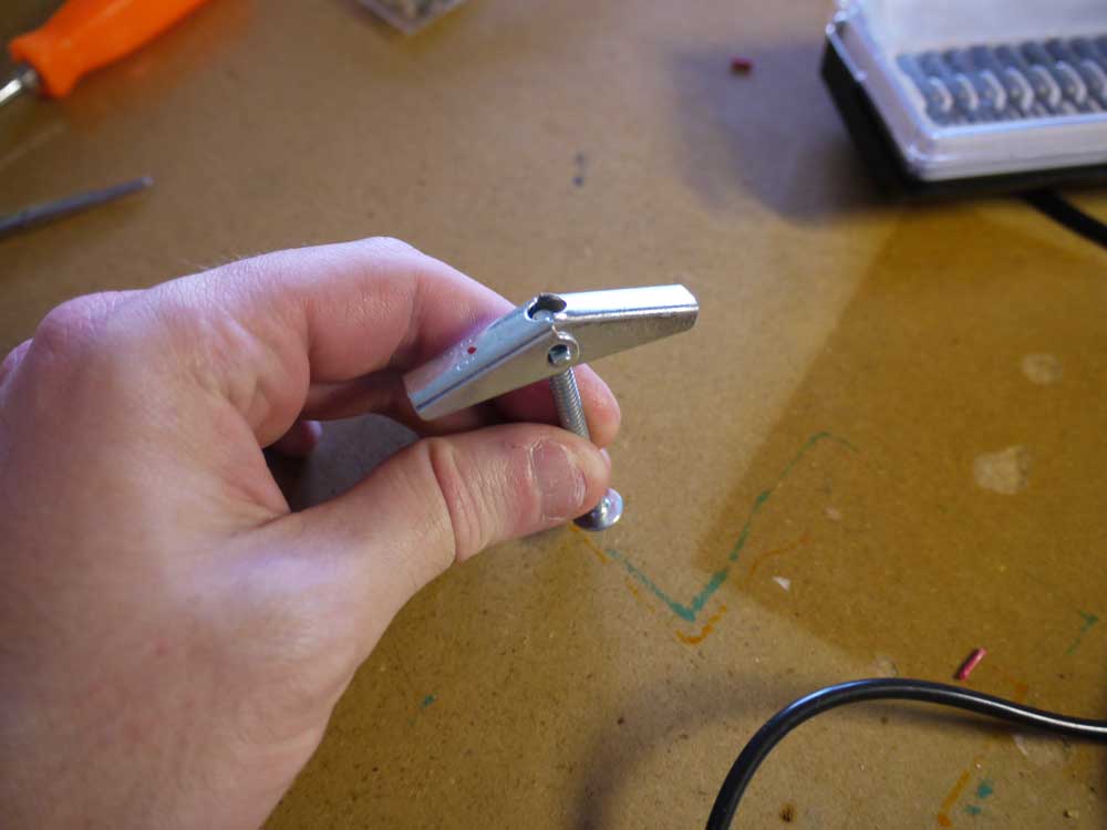
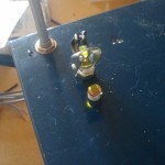
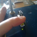
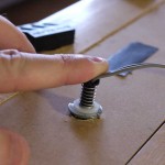
Goddamn Photoresistors: CDS photoresistors are cheap and easily available, but getting them to go through their resistance range smoothly is a real challenge. Early on, I discovered that if I moved a green LED closer or farther away from the sensor, it gave a much smoother response than if I tried to modulate the ambient light. So in my first attempt at creating a control, I used the humble toggle bolt. I mounted it up with the led on top and the photoresistor on the bottom, like so:
This worked okay in near or complete darkness, but not so much during the day–even ambient skylight is larger than the LED output by a few orders of magnitude. Which is a pity, because it would have looked cool, with all four levers mounted on the box and the wires coming out of them it had sort of a steampunk prosthetic hand look. It’s possible that I could have improved it by mounting the photocell on the lever and the LED below, but it had other problems as well– the levers needed some kind of extension on them to keep your fingers from slipping off them, and the whole assembly was kind of fussy.
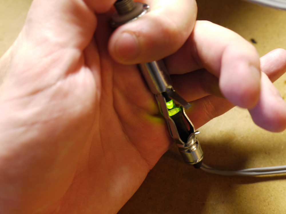
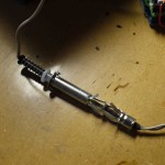
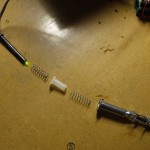
Next, I tried the hollow expansion bolts, with the LED and photocell mounted inside, like so:
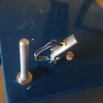
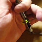
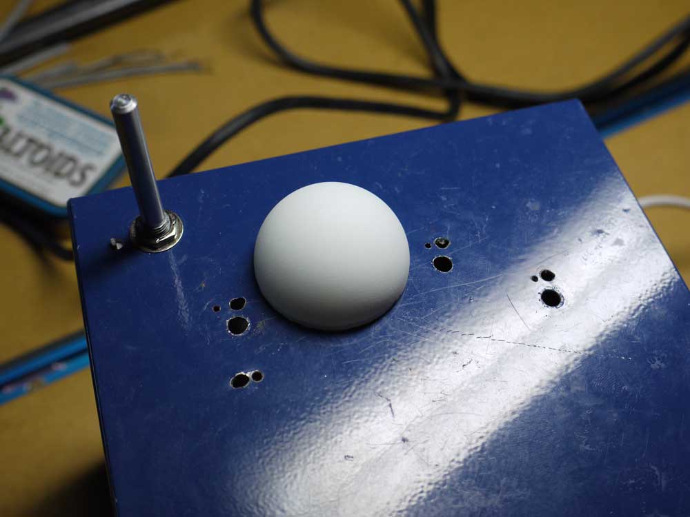
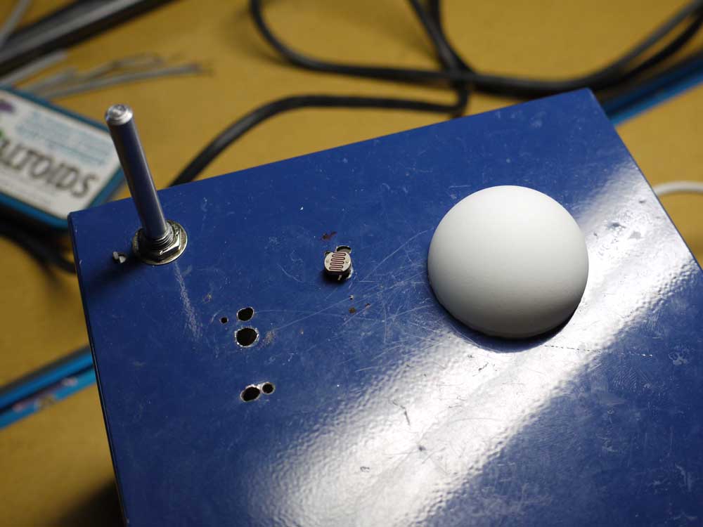
This works smoothly over a dynamic range of about 700 with the default analogRead() function. I’m thinking that I can put a tab on top of them to make them look like organ stops, which would be hot. I’m going to try manually configuring the Arduino ADC for 8-bit mode to try and squeeze a little more speed out of them– five sensors x 100μS + processing time with the default analogRead() function may make the loop too slow, and an 8-bit data format would be more convenient for processing anyway. The mechanism is going to be good for set-and-hold controls, but for the volume control I wanted something a little more dynamic, so prototype #3:
The ping pong ball does a excellent job of diffusing the ambient light so that the response is smooth.
I’ve made a number of unneccesary holes in the enclosure, and also scratched it up some. I’m not happy about that, and the lesson here is when you do a project that’s this complex, do a prototype. But I’m kind of enjoying working fast and sloppy, too.
